LRM Owner's Manual
LRM Owner's Manual
This document is in an expandable/collapsable format. This allows you to focus on a single area of interest without having to jump all over the map. Images are thumbnails and can be clicked to open a larger image in another window.</>
-
LRM Owner's Manual
-
Introduction
-
Welcome
-
General Information
-
Safety Information
-
-
Operation
-
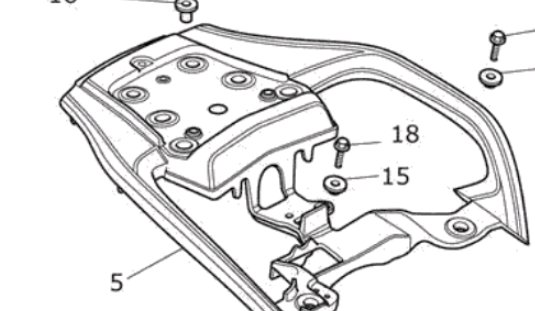
Mounting
-
Similar to BMW Top Case
-
-
Fuel Transfer
-
Filling
-
Venting
-
Fuel Shut Off
-
Quick Connect
-
Grounding
-
-
-
-
-
Installation
-
Bulkhead Fitting
-
K1600 GTL
-
1. Remove Main Fuel Tank
-
1. Remove Fairings
-
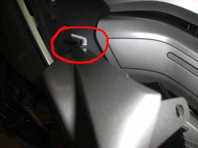
Remove lower panels (2)
-
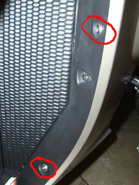
The front lower panel has four screws, two underneath, two inside the radiator opening (there are three screws inside the opening -- remove the top and bottom -- middle stays)
-
-
at the top rear of the front lower panel is a ~1" tall post that fits into a rubber grommet in the side panel. While relatively easy to get the right front lower down/out, with the optional fog light it is difficult to get the left front lower down/out without breaking the post -- go slow and don't apply bending forces to the post as you pull the panel down, and it will eventually come out.
-
-
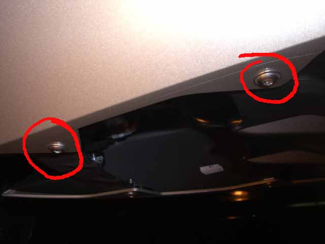
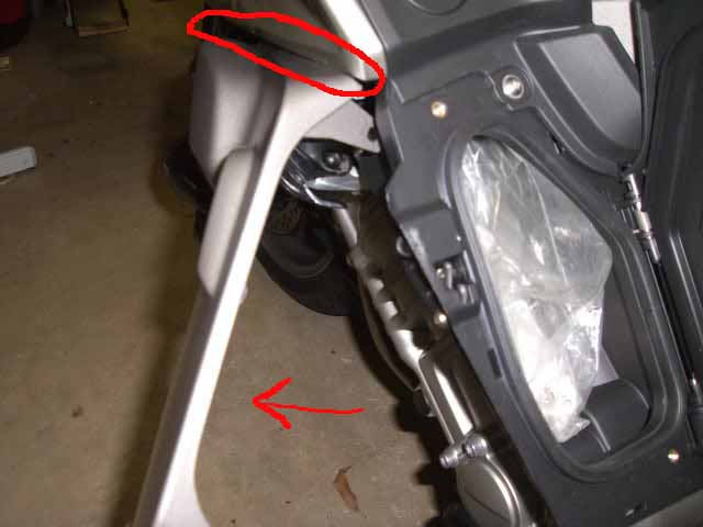
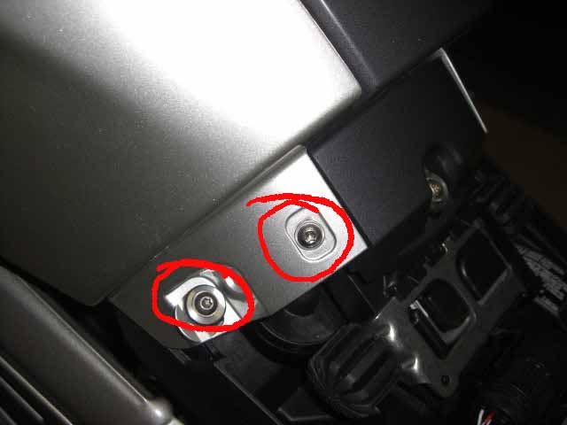
The rear lower fairing has three screws, two under the glove box door, and one at the front:
-
-
the lower has a hook on the top, so the bottom of the lower must be pivoted outward to release the hook from the panel above:
-
-
-
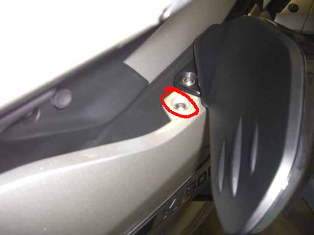
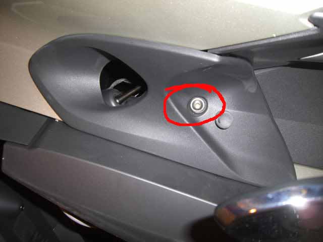
Remove Fairing Side Panels
-
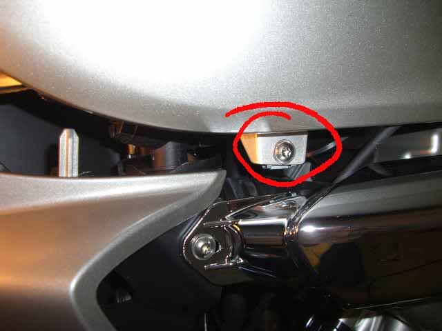
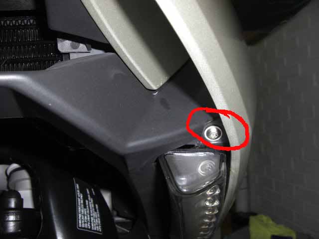
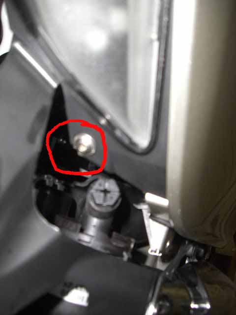
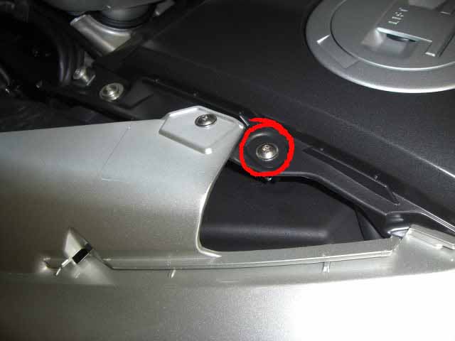
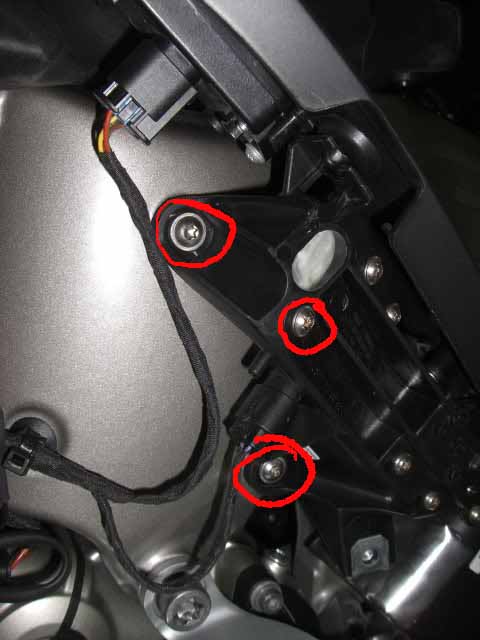
The fairing side panel has 7 screws around its periphery, 2 near the turn signal (top and bottom), 1 under the air deflector, 2 on the rear (rider) side of the panel, and 2 along the bottom of the panel.
-
-
-
Remove Air Intake Panel
-
remove the single screw holding the filler panel/air intake port, and slide the panel ~1" to the rear and lift out:
-
-
-
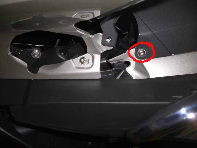
Remove Tank Top Panel (painted)
-
To remove the colored tank top panel, remove the two screws holding the top triangular "hump" panel, one next to the steering head, one under the filler panel, then slide the panel to the rear and lift off to disengage its tabs:
-
-
To remove the colored tank panel, start with the two small screws at the rear and the one on the top.
-
-
-
Remove Center Tank Panel
-
one long screw at the rear of the panel, and four at the sides of the panel near the fuel cap, then lift the panel up over the fuel cap.
-
-
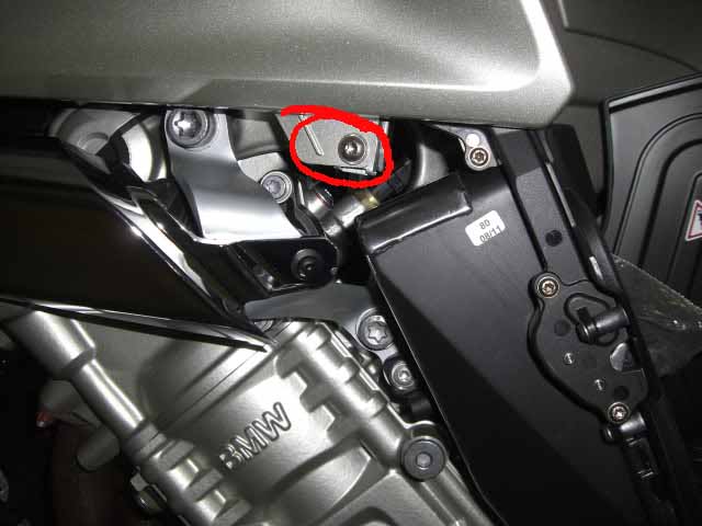
Loosen Side Trim Panels (2)
-
NOTE: These side panels DO NOT need to be completely removed to get the fuel tank out. Unless you need them off for some other purpose it is HIGHLY recommended that you just loosen them enough to move them out of the way for tank removal. The reason for this recommendation is that two of the bolts have stand off collars. The one that is deeply recessed is virtually impossible to reinstall. If you drop this collar when reinstalling you probably won't find it without some major disassembly. Pictures show left and right side panels ready for tank removal.
-
-
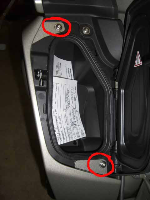
Four screws on each: one under the glove box door at the rear of the panel, one behind the slipstream deflector, and two recessed under the nose fairing.
-
-
The three upper screws are shown. The front one of the two recessed screws is relatively easy to reach. The rear is really hard to reach, follow the plastic of the panel back into the recess to find it. Having a T25 socket and a 10" 1/4" drive extension helps. These two also have collars you should keep track of.
-
-
I think there is a step missing here. It's been a long time but I think some of these screws need to come out as well. I need some feeback here ;-)
-
-
-
-
2. Remove Front Seat Support Tray
-
Remove the four Torx bolts on the bottom of the tray.
-
-
Cut the zip tie from that the diagnostic connector.
-
Lift out the tray.
-
-
3. Remove Air Box
-
There are three parts to filter housing: the air intake tubes, the filter holder front, and the throttle body box rear (the air intake tubes have been removed).
-
You can either remove the tubes from the air filter housing or remove the two air tubes and filter holder front as an assembly. Release the front of the air intake tubes by pulling them out of the front clamp arms.
-
-
The air filter housing and filter is removed by removing three T25 screws.
-
-
Lift the filter holder straight up and out
-
-
Remove the rear filter housing screw
-
-
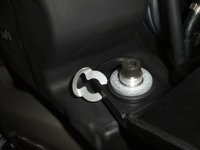
Next, the front retaining clips and washers must be removed from the two rear main tank supports -- the tank rear bolts pass through collars which do double duty, supports for the tank and hold-downs for the air box.
-
-
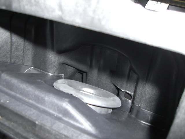
Once the clips and washers are off, look down into the rear air filter housing. You'll see a large round rubber gasket -- this is the box-to-throttle body gasket:
-
-
The trick to removing the rear box is to simultaneously pull the rubber donuts at the front of the box off the tank-mounting studs, lift the throttle body gasket up off the throttle body (note: at the angle it sits, the motion is more up and to the rear) and lift the rear bottom edge of the box straight up to get the rear of the box clear of the frame. If this all sounds self-contradictory, well it is. Bottom line, with slow steady pressure lift the box up and rotate toward the rear to get the rear of the box and the throttle body gasket to go up.
-
The rear of the airbox has a drain tube at the bottom which is routed to the left, to the area under the main frame on the left where the frame rail turns from horizontal to go down to the swingarm pivot (the drain line is a plugged line installed in the bike to allow periodic removal of any accumulated condensation from the airbox).
-
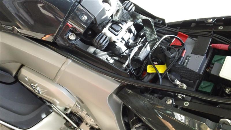
You'll also note a half-dozen wiring and hose connections to the box. I would advise disconnecting the air temp sensor connector at the front right corner of the box (underneath the box edge) to get more room to manuever the box after it's loose -- this connector has a short harness (push the wire bail inward to release the connector).
-
Once the rear box is loose, pull/twist/whatever to get some clearance when the tank is later lifted rearward for removal.
-
-
4. Remove Tank
-
Five connections must be removed: fuel level sender connector, fuel pump controller connector, fuel hose quick-disconnect, and two hoses at the fuel filler cap:
-
-
The filler cap hoses are simply pulled straight off their nipples, and pulled out of the little retaining tabs molded into the side of the tank. The wiring connectors have tiny, annoying retaining tabs -- lift and pull the connectors off. On the fuel disconnect, shove a rag or paper towel around the connector to catch the couple drops of gas that will be released, press the release tab and gently work the connector out -- be *sure* to hold the release tab the entire time you are removing the connector to avoid cutting the o-ring.
-
Remove the two rear tank hold-down bolts.
-
-
Remove the front hold-down bolt
-
-
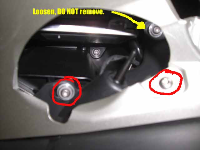
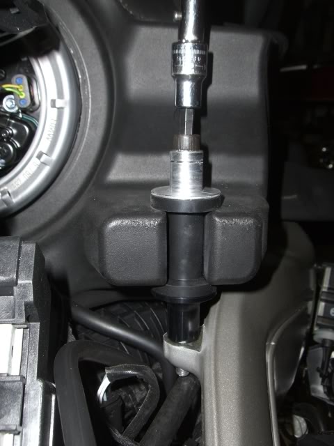
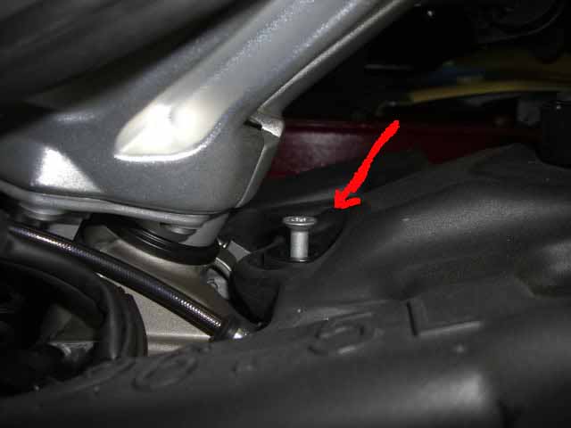
Loosen, but _do not remove_, the two T25 screws holding the air tube clamps to each side of the frame (4 screws total to loosen). Loosening these screws lets the two halves of each clamp assembly separate slightly, release their grip on the sides of the tank's small nose extensions (visible below, sticking out like fingers from the front of the tank).
-
Once the nose extensions are free, lift the rear of the tank up and draw the entire tank to the rear, and set aside.
-
-
-
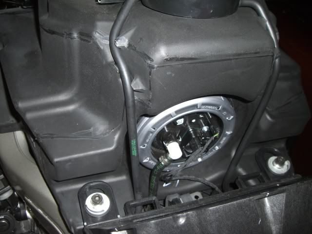
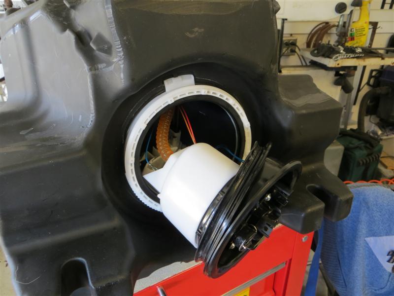
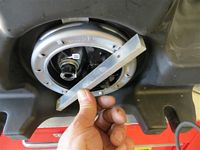
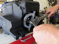
2. Remove Fuel Pump Assembly
-
Drain the tank. Remove as much fuel as you can.
-
Secure the tank or have a helper hold it in place.
-
-
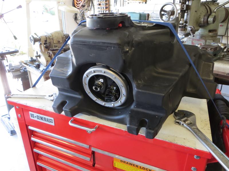
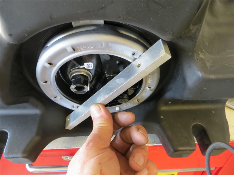
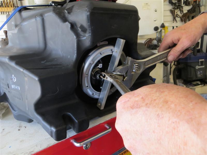
The fuel pump is secured in place with a threaded retaining ring. This ring might be loose enough to remove with your hands. If not, you will need to use some kind of spanner. If a spanner can't be fabricated then you can gently tap on the tabs to get this ring loose. Tap around each tab until you see some movement. Once it moves you can use your hands to unscrew it.
-
-
-
Note the position of the fuel pump before removing it so you will know how it goes back in.
-
-
Once the retaining ring is off you can gently pull on the tab to get a starting point for inserting a pry bar. Go around the edge prying the assembly out from the large O-ring.
-
-
The O-ring will likely come out with the pump. Be careful removing the pump to not bend or damage the fuel level float and assembly. Be patient and manipulate the pump to the correct position for removal.
-
-
Scavenge out the remaining fuel and dry the inside of the tank.
-
-
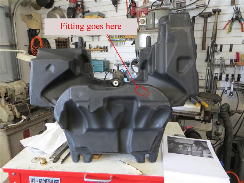
3. Locate and Drill hole for bulkhead fitting
-
The location of the bulkhead fitting is at the front left side of the tank. This position will allow the fitting and fuel line to clear the injectors and injector rail.
-
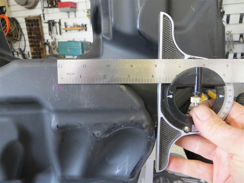
-
Measure from the front of the tank and make a line approximately 1-1/8" back from the front edge.
-
-
Measure from the left side of the tank and make a line approximately 4-1/4" towards the center of the tank.Â
-
-
Use a center punch to mark the intersection of these two lines.
-
Use a 3/4" spade drill and drill a hole at the marked location.
NOTE: While you can use any drill bit a wood spade drill bit will work best.
-
Use a sharp knife to debur the hole. Make sure you have a smooth, flat surface inside and outside.
-
Remove all debris from the inside of the tank.
-
-
4. Prepare Bulkhead Fitting
-
Install the right angle hose barb fitting into the bulkhead fitting. Use telfon tape or pipe joint compound (Oatey Great White with PTFE is recommended) on the pipe fitting. Tighten securely, you don't want leaks later on.
-
-
-
5. Mount Bulkhead Fitting
-
NOTE: The photos show the bulkhead fitting flange with the O-ring on the outside of the tank. While this is perfectly acceptable, it has come to our attention that it is better to put the O-ring on the inside. The plastic ABS tanks used on this model have some type of coating on the inside of the tank. It is possible for this lining to delaminate. By placing the O-ring on the inside you insure that fuel cannot leak between the lining and the ABS shell. We now use this method on all plastic tanks.
-
-
Place the bulkhead fitting in the hole with the O-ring on the inside
-
Place the lock washer and nut on the bulkhead fitting. DO NOT tighten yet.
-
Position the hose barb so it is pointed to the LEFT side of the tank.
-
Tighten the bulkhead fitting making sure you do not move the position of the hose barb. Since we have an O-ring seal this does not need to be tremendously tight. Just make sure it is snug enough that the barb doesn't move when you twist on it with your hand.
-
-
6. Replace Fuel Pump Assembly
-
Installation is the reverse procedure.
-
Put the O-ring back in the tank first (not on the pump or you will never get it in).
-
Make sure the O-ring is properly positioned. Sometimes it slips inside the tank druing your manipulations. Finding this error after everything is back together is not good.
-
Install and tighten the retaining ring. This doesn't need to be extremely tight. Just enough that everything is sealed but not so loose that it would work loose.
-
-
7. Attach Fuel Line to Bulkhead Fitting
-
Cut a piece of fuel line that will reach to the rear of the luggage rack.
-
Put the fuel line on the tank hose barb and tighten the hose clamp.
-
-
8. Aux Fuel Line Routing
-
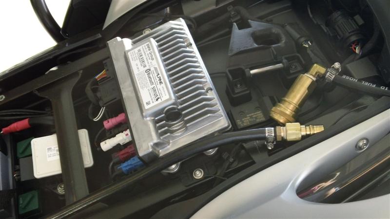
The aux line is routed along the left side of the bike inside of the frame. As you reinstall the tank you will see there is plenty of clearance for this line.
-
-
-
9. Replace Main Fuel Tank
-
Replace Tank
-
Install is the reverse.
-
When you are putting the rear air box back in, put your finger along the throttle body/gasket interface to ensure the gasket fits around the throttle inlet as the box is going back in. Also, be sure to hold the fuel line release tab in until the connector is fully seated, or you'll rip the side of the O-ring up as it passes the sharp edge of the metal release collar.
-
-
Reinstall Fairing Panels
-
Install is the reverse.
-
On the right side trim panel, don't forget to plug in the right power socket connector; it can be plugged in after installation of the panel, but it is easier done while the panel is still free.
-
-
-
-
R1200 RT
-
Remove Left Side Fairing
-
Remove Fuel Pump Assembly
-
Locate and Drill hole for bulkhead fitting
-
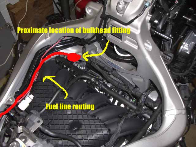
The location of the bulkhead fitting is at the rear on the lower left side of the tank. This position will allow the fitting and fuel line to clear the fairing when reinstalled.
-
There is a nice flat spot just above the left cyclinder adjacent to the tank mounting tab. This where the fitting goes.
-
Choose the flattest area you can in this area and mark the location.
-
Use a center punch to make a good dimple at this mark. If you don't center punch the drill can walk off of your desired location
-
Use a 3/4" spade drill and drill a hole at the marked location.
NOTE: While you can use any drill bit a wood spade drill bit will work best.
-
Use a sharp knife to debur the hole. Make sure you have a smooth, flat surface inside and outside.
-
Remove all debris from the inside of the tank.
-
-
4. Prepare Bulkhead Fitting
-
Install the right angle hose barb fitting into the bulkhead fitting. Use telfon tape or pipe joint compound (Oatey Great White with PTFE is recommended) on the pipe fitting. Tighten securely, you don't want leaks later on.
-
-
5. Mount Bulkhead Fitting
-
NOTE: The photos show the bulkhead fitting on the outside of the tank. While this is perfectly acceptable it has come to our attention that it is better to put the O-ring on the inside. The plastic ABS tanks used on this model have some type of coating on the inside of the tank. It is possible for this lining to delaminate. By placing the O-ring on the inside you insure that fuel cannot leak between the lining and the ABS shell. We now use this method on all plastic tanks.
-
Place the bulkhead fitting in the hole with the O-ring on the inside
-
Place the lock washer and nut on the bulkhead fitting. DO NOT tighten yet.
-
TBD
-
Tighten the bulkhead fitting making sure you do not move the position of the hose barb. Since we have an O-ring seal this does not need to be tremendously tight. Just make sure it is snug enough that the barb doesn't move when you twist on it with your hand.
-
-
-
-
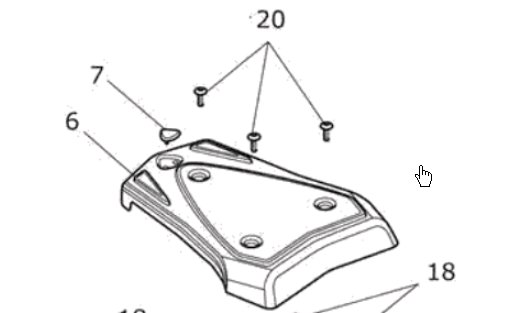
Mounting Plate
-
Tank and Optional Deck
-
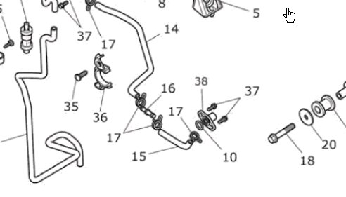
Fuel Line Routing
-
The aux line is routed along the left side of the bike inside of the frame. As you reinstall the tank you will see there is plenty of clearance for this line.
-
-
The fuel line will come alongside the fairing panel by the rider's seat area.
-
-
It drops inside the frame and runs underneath of the seat. Make sure when you are placing this line that you keep it clear of the seat bumpers. If the hose gets pinched, you won't get fuel flow.
-
-
-
-
Periodic Maintenance
-
Inspect Mounting Plate
-
Inspect Clamping Mechanism
-
Inspect for Leakage
-
-
-